
There have been three types of boiler used since Crofton started pumping in 1809. This page explains more about these three types of boiler including the current Lancashire boiler that you will see on a visit to Crofton.
The Waggon Boiler
Originally, Crofton had three of these low-pressure boilers working at 34.5 kPa (5 psi). The gravity boiler feed from the header pond at the top of the site to ‘standpipes’ on the waggon boilers is the reason why the original boiler house at Crofton is so tall.

The Waggon Boiler (so called because its shape was similar to the American Pioneer Waggon) was used by James Watt in the 1700s to power his stationary steam engines. It was one of the earlier designs of steam boiler. Like James Watt’s Engines, Waggon Boilers were not designed to run at a significant steam pressure. This was because little was known about pressure vessel design and because suitable material for their manufacture was only available in small sheets of variable quality. Thus Waggon boilers only provided steam at pressures of about 0.3 bar (5 psi) or less.

The diagram on the left illustrates the basic shape of the Waggon boiler (ignore the lightly drawn inner tube – that was a later development). Essentially, it was a rectangular box with a rounded top. It was fired underneath with return flues along the sides. Ash from the fire dropped into arched chambers below the boiler from which it was removed by wheelbarrow.
The ash pits for the Waggon Boilers still exist at Crofton (they are part of the ‘undercroft’) but they are not suitable for general public access as they are very cramped.
The Cornish Boiler
The Cornish Boiler was one of a number of different designs of boiler developed to produce steam at a much higher pressure than Waggon and the Haystack boilers. Developed by Cornish engineer Richard Trevithick in 1812, Crofton had five Cornish boilers after the modifications of the 1840s.
Cornish boilers consists of an iron tube of some 1.5 m (5 ft) in diameter and about 8.5 m (26 feet) long enclosing a single cylindrical furnace tube of 90 cm (3 feet) in diameter. The fire burns on a cast iron grate inside the first 1.8 m (6 ft) of this tube. Gasses from the fire pass down the tube, are diverted at the end into brick flues down the side of the boiler, then back down a central flue under the boiler before escaping to the chimney. The furnace tube served the dual purpose of conducting the heat from the fire into the water surrounding it and preventing the end plates of the boiler from bulging outwards from the pressure of steam.
The Lancashire Boiler
Between 1893 and 1903 the five Cornish boilers at Crofton were replaced by two Lancashire boilers. In turn, one of these was replaced with a similar second-hand boiler in 1987.
Lancashire Boilers are similar to, and derived from, the Cornish boiler in that they have tubular metal furnaces passing through a horizontal cylindrical water space with external multiple pass flues. However, they differ from Cornish boilers in that they have an additional furnace tube, a different gas path and they are larger. The engineer Sir William Fairbain developed the Lancashire boiler in 1844. Crofton uses a Lancashire boiler, and has a spare shell on site held for the future. Both of these boilers are some 2.3 m (7½ ft) in diameter and 8.5 m (28 ft) long and weigh about 22 tonnes. They have a working water capacity of some 18,000 litres (4,000 gallons/18 tons). These dimensions are typical for boilers of this type.
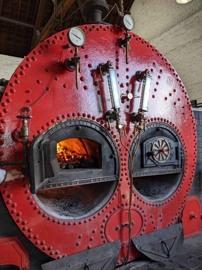
The two cylindrical furnaces can be seen, they are 70 cm (2 ft 4 inches) in diameter. They have two functions:

- To transfer the heat from the hot fire gasses to the water surrounding them.
- To help prevent the end plates of the boiler from bulging outwards.
The fire itself is only about 1.8 m (6 ft) long with a total grate area of 2.8 m2 (30 sq. ft) and sits upon firebars made of cast iron. It is retained by a low firebrick wall. The external flues are made of brick and the top, exposed part of the boiler shell is covered in special insulating fire bricks.

From these diagrams, it can be seen that the gas path of a Lancashire boiler differs from that of its predecessor, the Cornish boiler, in that the hot gasses from the fire pass under the boiler first, then back down the sides. With the Cornish boiler, they go down the sides first then back down under it. Thus, a Lancashire boiler has two fire damper plates, one in each side flue, compared to the Cornish boiler’s single damper plate in the under-flue.


The original Lancashire boilers at Crofton differed slightly from the above design, in that they had Fox’s corrugated furnace tubes which although better at resisting crushing pressures and transferring heat, were not able to act as end reinforcements. These boilers were therefore fitted with massive nutted stays that ran their length. These stays can be seen on the sectioned example in Crofton’s Side Boiler House. This latter boiler is particularly interesting, in that it has a ‘Cornish’ gas path (i.e. it has only one, central damper plate). This modification was probably adopted because the boiler was installed over the bed of the Cornish boiler that preceded it.
Corrugated furnace tubes were introduced on some later boilers to help prevent crushing as working steam pressures increased. Another type of design, that was introduced for the same reason, was the use of short, flanged tube segments, known as Adamson Rings, after their inventor.